Blog

We have integrated a hybrid battery storage system into our home which is designed to supply permanent 12V and 240V to key electrical circuits. Read on to learn how we have built this system.
Safety
First and foremost before we get started please be aware that when working with solar panel arrays typically they are connected in series meaning they are high voltage. In our case we have two banks of 1200 Watts that sit at about 100 Volts. It is incredibly important that if you don't want to be a temporary citizen that you take the necessary precautions to isolate the solar array from the charge controllers anytime you work on a system. Once isolated allow a few minutes for the charge controller's capacitors to discharge.
Battery System Location
We have installed our battery system in a hall cupboard inside our house. There are a few reasons for doing this. Firstly batteries like to be kept at a stable temperature and optimally should be as close to 25 degrees celcius as you can keep them. Secondly this environment can be kept clean and access for checking and maintenance makes it much safer for working on when necessary. Lastly its a good central place that all cabling can be safely routed in and out from the roof space.
The batteries we use are safe for using in enclosed spaces as they do not vent hydrogen. In any case our battery cupboard is vented constantly via two 12V 100mm "computer case" fans. One sits at the top of the cupboard door and sucks the hot air out. Another sits at the bottom and blows cool air in. This is important not just for ventilation purposes but helps keep the equipment like the charge controllers cooler as they generate a fair bit of heat.
Battery System
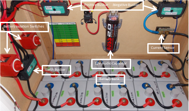
Our battery system is made up of 12 x 2 Volt 790ah Lead Acid Gels. These are in a configuration of two banks of 6 connected in series to create a nominal voltage of 12.6V with both banks then connected in parallel for a total capacity of 1580ah. This equates to a theoretical capacity of around 18kwh. Taking into consideration that we do not discharge below approximately 50% SOC this gives us about 9kwh. Then taking into further consideration inefficiencies caused by the Peukert Effect our experience has shown we get about 8kWh for every cycle. We can of course take more from the system if we wanted to but this just reduces the battery cycle life.
The components used -
- Busbar - these are four post M10 500 amp busbars.
- Isolation Switch - these are Blue Sea Systems 300 amp isolation switches. We use one switch per bank so each bank can be isolated independently.
- Current Sensor - this is a Midnite Solar current sensor that connects to one of the two Midnite Solar Classic 150 solar charge controllers. This is used to accurately monitor or power that goes in or out of the battery bank.
- Audio Capacitor - this is a two Farad audio capacitor that is a bit of an experiment. Capacitors have extremely fast charge and discharge capabilities, much more so than batteries. The idea is that the capacitor helps smooth out rapid changes in voltage caused by load or supply changes. There is a 50 amp thermal isolation switch so that capacitor can be isolated if required.
- Wiring - all wire that interconnects the batteries themselves and to the isolations switches and busbars is 2B&S (200 amp).
Solar Charging System
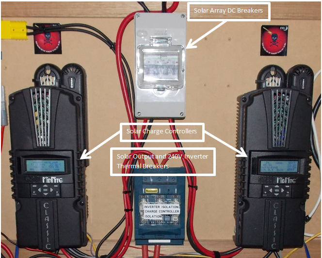
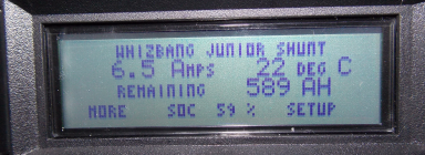
Based on our battery size we have two independent 1200 Watt solar arrays. Each array is made up of 6 x 200 Watt panels connected in series. This provides an output voltage of around 100 Volts and 18 amps. This is connected to our two Midnite Solar 150 Classics using twin core 6mm2 solar wire. Each array is connected to its own 30 amp DC breaker. This allows the safe isolation of each array to its charge controller. In our view if you have the money we strongly recommend the Midnite Solar charge controllers. These are the best in the business. Designed and manufactured in the United States they are super robust and perform exceptionally well. The current sensor is a "Whizbang Junior" and is connected to the controller on the left.
Generally we will see around 120 amps produced between the two controllers when charging in bulk mode (controllers have a maximum output of 90 amps each). This then tapers off steadily as the batteries go into the absorb state. Based on an average of use of 5kwh overnight it takes around six hours for a complete charge (float). It is important to understand the charge cycle is not linear. The absorb cycle can take the bulk of the time.
The important thing to take into consideration is always size your controllers carefully and aim to only use around 70-80% of its capability. This is necessary for a few reasons.
- Constantly running your charge controller at its maximum output will shorten its life due to heat and component stress.
- There is phenomenon called cloud edge effect for solar input. This is where the sun starts peeking out from behind clouds. The water droplets in the air act as magnifying glasses and can briefly cause a surge in power output from the panels that could exceed your controllers input capabilities potentially causing damage.
- Cold conditions improve solar array efficiency. This can cause higher than normal voltages being experienced. The colder it gets the more performance you get which can be a bad thing if the array is not sized to take this effect into consideration.
The components used -
- Solar - two banks of 6 x 200 Watt solar panels
- Charge Controllers - 2 x Midnite Solar 150 Classics
- Solar Isolation/Safety - 2 x 30 amp DC Breakers
- Charge Controller Output Isolation/Safety - Bussman 160 amp thermal breaker
- Wire - 6mm2 Solar DC Cable from solar array to controllers, 16mm2 from controller to common busbar.
240V System
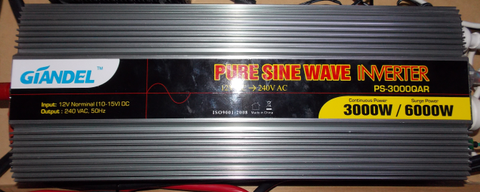
This is not an overly complicated component of the system. We use a 3000 Watt pure sine wave inverter to supply 240V to select GPO outlets in our house that includes -
- Kitchen Refrigerator
- Office Computer Equipment
- Internet Equipment
- Pellet Fire Heater
- Air Circulation System
The great thing about using pure sine wave inverters as they supply very stable clean output which is always much better than grid power. You will not experience equipment failures due to voltage surges. The inverter we use is way oversized for our needs but again because of its light use it will provide a long service life. The one thing to understand about inverters is they have a parasitic load. That is they consume power even if they are to providing a supply to devices. This varies based on inverter efficiency. Generally the better quality inverters are more efficient. If you do not need to use 240V then it is recommended to turn it off.
Whilst we use a cheap inverter we do recommend either Victron or Renogy branded.
12V System
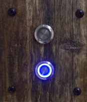
Pretty much all lighting in our house has been converted to 12V. The best place to source 12V lights is definitely marine shops as the quality will be excellent. Light switches have been replaced with stainless steel push blue ring button style. We also run 12V to a number of USB outlets for charging of electronic devices and also for fans and small lights. All 12V circuits go through two independent 12 port blade fuse holders in the roof. Each blade fuse holder is direct connected via 16mm2 DC wire.
The components used -
- Fuse Block - 2 x 12 port blade style fuse block
- Wire - 16mm2 to fuse blocks and 4mm2 to lights and USB ports.
- Isolation - 2 x 50 amp thermal breakers to isolate blade fuse blocks.
Auxilliary Charging
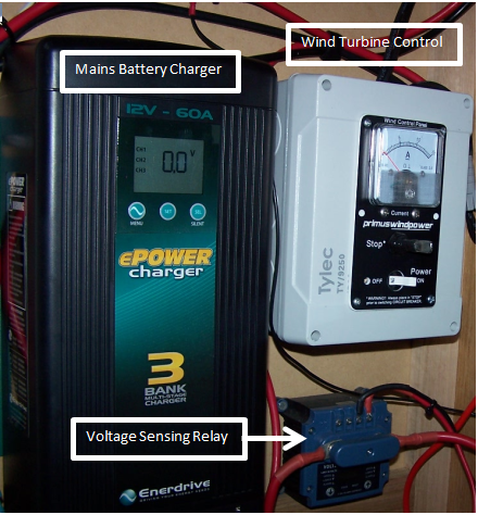
Finally to ensure our batteries never drop below a certain voltage we have integrated a grid connect battery charger. This is controlled by using an Intervolt Programmable Voltage Sensing relay. The battery is connected through the relay to the mains charger. When the voltage hits a certain low (11.9 Volts) it will connect the battery to charger and it will start supplying energy. Once the voltage reaches an upper value (13.1 Volts) it will disconnect the battery from the charger. The idea here is to not let the charger fully charge the batteries but rather provide an emergency supplement to protect the batteries from over discharge. If you where off grid you can connect an auto start from the Intervolt relay to the generator start circuit.
Of course this wouldn't be complete without our Wind Turbine. This has been a reliable Marine Grade Air-X Marine which is now five years old. It will be upgraded soon to a larger TESUP Master940.
The components used -
- Mains Battery Charger - this is a good quality Enerdrive ePower 60 amp charger.
- Relay - Intervolt 150 amp programmable voltage sensing relay, the best of the best and the only high quality relay we recommend.
- Wind Turbine Control - Primus Windpower start/stop and isolation switch.
- Wire - 16mm2 from battery to relay and also to battery charger.
If you are looking at setting up your own battery system but aren't sure what you need why not contact us? We can provide a consultation service to get you on the right track.
Comments
- No comments found
Leave your comments